
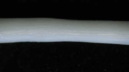
Figure 1: rough surface on TPU filament
1. Surface defects
Surface defects in the die land area can be caused by scratches, burrs, or foreign material in the die/nozzle. The defect causes an indentation in the filament that remains in the same location over time. If the problem is due to a foreign particle on the nozzle edges or in the nozzle, clean the nozzle and die to eliminate the problem. Any scratches in the nozzle area have to be mechanically removed to eliminate the problem, but often it is easier to order a new nozzle package.
Nozzle packages and different sizes are available on our shop.
(only available in the Schengen region)
2. Nozzle build-up
Lines/streaks on filament might also be caused by a phenomenon called nozzle lip build-up (Figure 2). This is when material remains around the edges of the nozzle, and seems to keep returning even after it is physically removed. This usually because the nozzle temperature is too low for the material which is being processed. This is especially problematic with semi-crystalline polymers because if the nozzle is below the materials melting point, it is very likely that the material that gets in contact with the nozzle solidifies again.
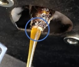 Figure 2: Nozzle build up
3. Streaks caused after extrusion
A machine direction streak may be caused outside the extrusion unit and nozzle, by dragging the product across something in the sizing operation (filament sensor and puller wheel) or on the take-up unit (positioner and winder). This is usually fairly easy to detect and correct. If the scratch is not present as the filament exits the nozzle but is seen partway down the line or on the spool, the problem is not in the nozzle. Determine where or what is scraping or damaging the filament surface after it leaves the nozzle and eliminate the problem. The most common cause here is a damaged puller wheel, see figure 3.
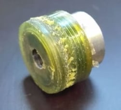 Figure 3: Damaged puller wheel
If the puller wheel’s surface is not smooth, this may cause streaks/lines on the filament. The only way to fix this is by replacing the puller wheel with a new one which can be bought at
When you have a new puller wheel available you can use the following guide to change the wheel.
4. Distortion of filament form
Another reason why the produced filament has a rough surface is due to a distortion of the filament form. This distortion can have two causes.
Sharkskin
Sharkskin is a phenomenon that can be recognized by the appearance of ridges present on the produced filament. This is also presented in the figure 4.
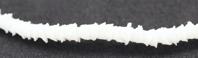 Figure 4: Sharkskin
Sharkskin happens when the outer layer of the filament moves slower than the inner layer. When this happens, it causes melt tearing resulting in the sharkskin. To avoid this from happening, the temperature of Heater 1 can be increased, reducing the chance of melt tearing and sharkskin. Another option is reducing the temperatures of all heaters; this will result in a more elastic output, preventing melt tearing.
Melt fracture
Another phenomenon that distorts the filament form is called melt fracture. This phenomenon is recognizable by the appearance of helical distortion on the outer layer of the filament. The distortion can be so severe that the filament spirals or small ripples appear. The figure below shows this.
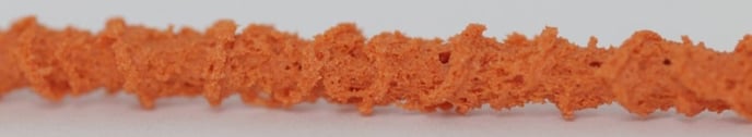 Figure 5: Melt fracture
Melt fracture occurs when the shear rate exceeds the critical shear rate. The critical value can be determined using a shear-rate/shear-stress diagram. When melt fracture is observed the following steps could help to solve the issue.
Increasing the temperatures of all heaters.
The critical value increases when the temperature rises; therefore, the shear rate will end below the critical point, solving the melt fracture. The temperature of Heater 1 plays an essential part in the melting of the material. Therefore, only increasing the temperature of H1 could also prevent the melt fracture.
Decreasing the screw speed
When reducing the screw speed, the shear rate decreases, reaching below the critical value and thereby solving the melt fracture.
5. Chart of potential causes and corrective actions
Figure 6 summarizes the potential causes and corrective actions to employ when the surface of the produced filament is rough.
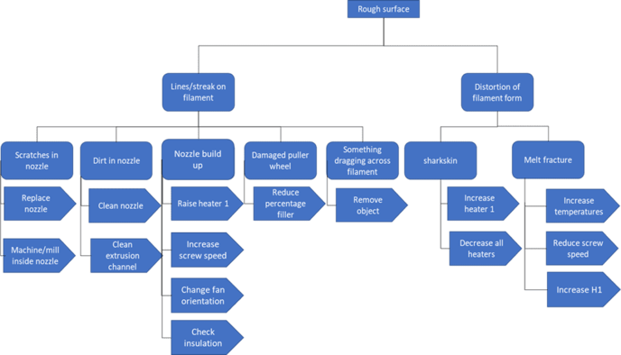 Figure 6: Summary of possible issues and corrective actions when encountering a rough surface on the filament