1. Lack of cooling
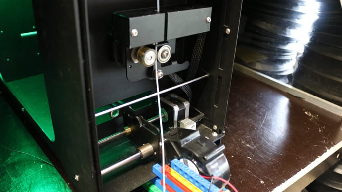
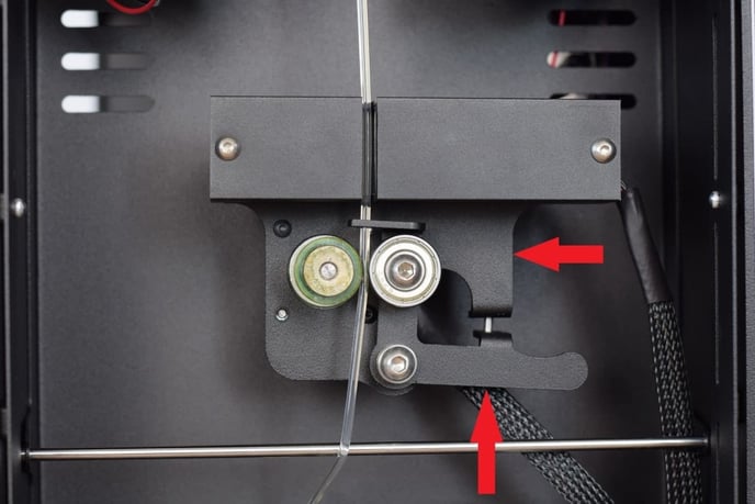
A lack of cooling is the first and easiest cause to identify. If the extruded filament is still too hot and therefore too soft/deformable, it can become flattened by the puller mechanism. This cause can be identified by taking a closer look at the front of the machine (where the filament comes out). If you can see that the filament is only deformed by the puller wheels and not elsewhere, a lack of cooling is often the case. This can easily be fixed by increasing the filament fan speed. If for any reason it is not desirable to increase the fan speed, it is also possible to decrease the clamping tension of the puller wheel mechanism. The pressure of the puller wheel on the filament is adjusted by a bolt and nut. If you loosen the bolt, there will be less pressure on the filament (Figure 1).
2. High polymer crystallinity
High polymer crystallinity is often the cause for why filament becomes oval, flat, or distorted when leaving the machines nozzle. This deformation can occur at the puller mechanism, but often also before (so during the cooling process). All polymers/plastics consist of molecular chains. The way these chains are ordered depend on the type of polymer, and can be arranged in an amorphous way or a crystalline way.
- Amorphous polymers
- Crystalline structures
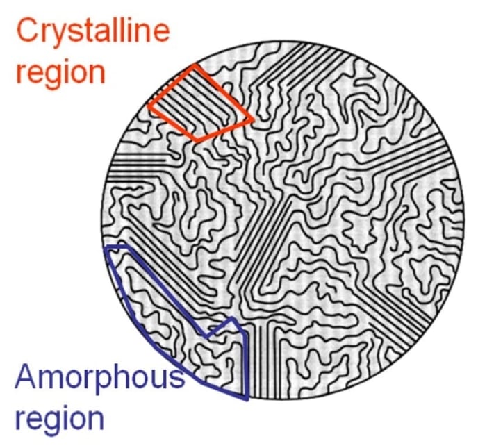
These molucular chains are generally very ordered, which is what gives them strength and rigidity. Think of diamond or steel as examples. A crystalline polymer, where the molecular chains are largely locked in place against one another, is similar. Apply a load and it will break rather than bend (Mallard Creek Polymers, 2017). Polymers can never be fully crystalline, it always consists of crystalline and amorphous regions (Figure 2) which is why these polymers are often called semi-crystalline. The size and amount of the crystalline regions determine the crystallinity of the polymer. The more the polymer consists of these crystalline regions, the higher the polymer crystallinity.
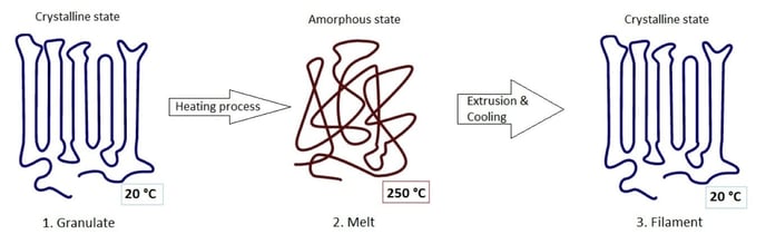
Semi-crystalline polymers such as POM (Polyoxymethylene) and HDPE (High Density Polyethylene) that naturally have a very high level of crystallinity, usually come with deformation problems in the form of oval or flat filament. This is a result of the extrusion process. In Figure 3 you can see the state of the material during the extrusion process. The first step visualizes the crystalline structure of the granulate, for example HDPE. When the material is heated up inside the extruder, the polymer chains loosen up and form an amorphous structure, allowing the material to melt into a viscous liquid. In this state the material will be extruded and formed into filament as it exits the machines nozzle. When the material has exited the nozzle, it immediately starts to cool down as the atmospheric temperature is way lower than the temperature inside the extruder. During this cooling process, the material cools down to a certain crystallization temperature. As the name suggests, this is the point where the material wants to form back into its naturally semi-crystalline structure.
Now the amount of crystallinity is also determined by how much time the material has to form back into its semi-crystalline structure. This period of time is determined by how fast the material is being cooled down. If the material is cooled down very fast, the time period wherein the material is within the crystallization temperature range is very short. This means that the material does not have much time to form back into its original amount of crystallinity, and sort of freezes in its amorphous state. This cooling and crystallization process (the transition between step 2 and 3, Figure 3) comes with a phenomenon called ‘shrinkage’. If a material is forming into a more crystalline structure, the material is also shrinking. This is because the density of a crystalline structure is higher than that of an amorphous structure. For example, HDPE in a crystalline state has a density of 1.0 g/cm 3 (grams per cubic centimetres) and HDPE in an amorphous (molten) state has a density of 0.85 g/cm 3. The problem with this phenomenon called shrinkage is that it is very hard to make sure that this shrinkage happens uniformly. If the amount of shrinkage in the filament is not uniform, it causes the filament shape to become oval, flat or distorted. Non-uniform polymer shrinkage can be caused/influenced by the following subjects:
- Molecular orientation
- Reinforcing fibers and fillers orientation
- Cooling uniformity
- Melt temperature uniformity
2.1. Molecular orientation
Extrusion tends to align the polymer molecules more in the machine direction than in the transverse direction. Polymer molecules aligned in the machine direction have higher shrinkage than in the transverse direction. This shrinkage difference can cause the part to twist or deform. Assume one side is being pushed out the nozzle faster than the other side; this leads to different molecular orientation across the filament and different shrinkage, leading to filament deformation. The slower side is stretched more, resulting in higher molecular orientation. In Figure 4 a schematic visualization of this phenomenon is given. Polymer molecules are oriented by stretching or pulling the polymers in a given direction, but the stretch in any direction has to be equivalent to prevent deformed filament. The problem with this phenomenon is that it is nearly impossible to detect. At this point the only known reason for these velocity differences in the nozzle is dirt (left material or carbon that does not belong there) or damage inside the nozzle (as visualized in Figure 4).
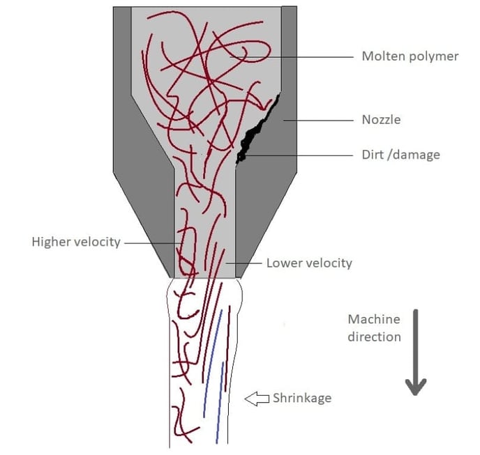
Dirt accumulation inside the nozzle also implies why it is very important to purge the machine every now and then, so the extrusion channel will become dirt free and improves the quality of the extruded filament. Damage of the nozzle can occur as a result of wear, especially during the use of very strong engineering polymers (for example PEEK or PEKK) or polymers with fibre fillings. Under high pressure, material keeps scratching the inside of the nozzle during the extrusion process, which is also why it is recommended to replace the nozzle once in a while.
At the 3devo test lab the nozzles of the machines which are used for material research, are replaced at least every month (these machines are running 30 hours a week), and if there is suspicion of a damaged nozzle it will be replaced without hesitation.
2.2. Reinforcing fibres and fillers orientation
It is a general known fact that 3D-printing filament containing fibers or fillers, actually prevent warpage of the part during the 3D-printing. However, for the production of this filament, it can actually be an obstacle. If the to be processed material is filled with fibre reinforcements or fillers with an aspect ratio (filler particle length to diameter ratio, L/D) greater than 1, the reinforcement causes the resin matrix shrinkage to be anisotropic unless the filler or reinforcement is completely randomly dispersed. The pulling or drawing action in the nozzle aligns more fibres or fillers in the machine direction than in the transverse direction, resulting in a shrinkage difference between the two directions with a high probability of deformed or oval filament. Since mineral fillers and reinforcing fibres have lower shrinkage than plastics (by at least one order of magnitude), shrinkage is now greater in the transverse direction compared to the machine direction. The shrinkage difference between the machine and transverse directions can lead to deformations in the extruded filament.
2.3. Melt temperature uniformity
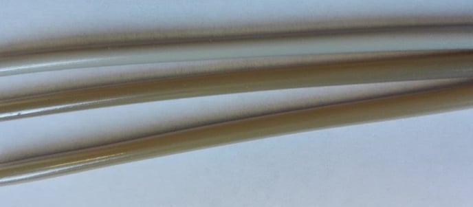
If the melt temperature on one side is hotter coming out of the nozzle than the other side, deformation and oval filament can result even with uniform cooling, as the hotter side may solidify later in the process compared to the side with the cooler melt temperature. Uniform melt temperature criteria are important to minimize deformation. This also has an effect on the uniformity of crystallinity of some polymers, and thus also the uniformity of the shrinkage of the filament. The non-uniform crystallinity is visible because of the color differences on the filament (Figure 5 shows a rather extreme case with the material PAEK). In general, the more crystalline a polymer gets, the more opaque it will become.
2.4. Cooling uniformity
Crystalline materials need to be cooled uniformly to generate the same crystallinity and crystal size. If the crystallinity is higher in one section compared to another due to cooling differences, the section with higher crystallinity will shrink more. This will cause the filament to become oval, and this is also the most probable reason for why your filament is oval or flat shaped. The current cooling system of the filament maker unfortunately possibly contributes to this problem, as two air fans cooling from two directions directly under the nozzle is not a very uniform solution. Two opposite sides of the filament undergo the most cooling and thus less crystallinity which means less shrinkage. The other sides undergo less cooling and thus more crystallization and shrinkage. To solve this problem, more even cooling must be achieved. In the 3devo-lab very positive results have been booked by using a 3D-printed fan modification (see Figure 6). This 3D-printed part generates a circular cooling effect, so the filament is being cooled from all sides more evenly.
3. What does this mean for your Filament Maker?
After reading this document it now should become clear that this is quite an abstract subject. All the possible causes have now been discussed, but the next challenge is to translate these theoretical causes into practical solutions/possible corrective actions.
To find specific practical solutions way more research into the behavior of semi-crystalline polymers will be necessary. But as already mentioned in the previous paragraph, there are ways to improve the extrusion process and thus minimize the oval or flat shaping of the extruded filament. These ‘possible improvements’ can be deducted from the subjects from previous paragraph. Below follows an ordered list of possible corrective actions, which can reduce the oval and flat shaping effect.
This list applies to semi-crystalline polymers, and excludes actions related to paragraph 1, ‘Lack of cooling’. Also please note that these actions might not completely fix the problem, and the grade of improvement might depend on the type of semi-crystalline material.
3.1 Keep the extrusion channel clean
Keeping the extrusion channel clean is the first action that should be taken in order to reduce the oval shaping effect. This way the molecular orientation as discussed in paragraph 2.1 will be as uniform as possible. Please refer to our cleaning manual for more information about this subject.
It is also recommended to replace the nozzle every now and then, or if you suspect that the nozzle is damaged or contains dirt that is stuck.
(only available in the Schengen region)
3.2 Reduce filament output speed
Reducing the filament output speed by lowering the extruder RPM can decrease the flow speed differences as discussed in paragraph 2.1. Less flow speed difference means less difference in molecular orientation, which means smaller shrinkage differences in the filament.3.3 Reduce percentage of fibers and fillers
As discussed in paragraph 2.2, fibers or fillers (if present in material) can cause the shrinkage to be anisotropic because fibers and fillers have lower shrinkage than most plastics. Reducing the fibers or fillers in the plastic before extruding it, can have a positive effect against the oval or flat shaping effect.3.4 Minimize filament output temperature
Minimizing the filament output temperature is also a good approach to minimizing the oval or flat shaping effect of the filament, and can be derived from the theory discussed in paragraph 2.
Paragraph 2 explains that a crystalline polymer is in an amorphous state when above melting temperature, and immediately wants to form back into its original semi-crystalline structure when cooled below melting temperature. By minimizing the filament output temperature, the oval or flat shaping effect as a result of non-uniform temperature distribution (as discussed in paragraph 2.3) in the extruded filament will also be minimized. This is because a lower overall temperature of the filament also means that temperature differences inside the filament will be smaller, and smaller temperature differences mean smaller shrinkage differences in the filament.
Minimizing can be done by starting the extrusion process with the regular temperature profile, and then gradually decreasing the temperatures of heater 1 and heater 2. This should be done in steps with a maximum of 5°C. By doing this gradually you can spot earlier when to stop decreasing the temperature, because the material flow then also starts to decrease. There is of course still the risk of going too low with the temperatures and blocking the material flow completely, and it can also cause the nozzle to be pushed out.
3.5 Cooling more uniformly
As mentioned in paragraph 2.4, using a circular cooling mod is a very effective method for achieving more uniform cooling. This uniform cooling can decrease the oval or flat shaping effect, on the condition that all previous steps have been followed. This is because cooling more uniformly is only an external improvement. If the filament itself has the tendency of forming into an oval shape, not even perfectly uniform cooling can prevent this.
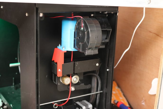
Another option (besides the circular cooling mod) is placing one of the cooling fans from beneath, like in Figure 7. This is a good option if you don't have a 3D-printer available.